Shop


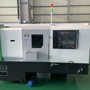
FFG DMC DL45LM Heavy Duty Horizontal Turning Center
Description
The DL 45LM is designed by FFG DMC with years of expertise and the latest technology, is designed to maximize productivity by enhancing both technical performances. All axes of DL 45LM is designed with Box Guideway and providing more accurate cutting performance.
■ FEATURES
- Fanuc 0i-TF Plus controller
- 4” LCD Monitor
- Powerful spindle
- 18” Chuck / A2-11 / 2,000 rpm spindle
- 50 Hp (37 kW) spindle motor
- Torque 2,173 lbf-ft (300.4 kgf.m) – 2 step gearbox belt driven
- Ø4.59” (Ø5 mm)Bar capacity
- Ø24.41” (Ø 620mm)Max. turning diameter
- 17” (2,265mm)Turning length
- BMT 75 Servo Turret – 4,000 rpm – 15/ 10Hp (11 / 7.5kw)
- 12 Station Servo Turret
- A2-11 Spindle Nose
- Box Guide Ways
- Programmable Tail Stock
- Programmable Quill
- Tool size: □26”/Ø 2.36” (□32mm/Ø60mm)
- 3 color tower signal light
- 787 IPM (20m/min) X, and 708 IPM (18m/min) Z rapid traverse
- 45° slanted All-in-One Bed structure
- Manual Guide i
- Chip Conveyor
- (4) Extra M-Codes
- Air Gun
- Coolant Flushing Gun
- Oil Skimmer
- Auto Tool Pre-seter
- Steady Rest Preparation
- Fanuc two years warranty
■ SPECIFICATIONS
CAPACITY:
Maximum Swing (on the Bed) Ø 775 mm (30.51”)
Maximum Cutting Diameter Ø 620 mm (24.41”)
Maximum Cutting Length 2,265 mm (89.17”)
Draw Tube I.D. Ø 120 mm (4.72”)
Bar Capacity Ø 116.5 mm (4.59”)
Chuck Size 18”
SPINDLE:
Spindle Nose A2-11 (ASA)
Bore Diameter Ø 132 mm (5.2”)
Main Spindle Motor 37/30 KW (50/40 Hp)
Spindle Speed 2,000 rpm
Spindle Torque (15 min. rating) 2,173 ft-lbs (304 kgf.m)
SLIDE & CARRIAGE
“X” Axis Travel 350 mm (13.78”)
“Z” Axis Travel 2,330 mm (91.73”)
Rapid Traverse “X” 20 m/min (787 IPM)
Rapid Traverse “Z” 18 m/min (708 IPM)
Guide Ways (X / Z) BOX WAY
Bed Structure 45o Slant bed
BMT 75 TURRET
Max Number of Tool Stations 12 Tools
Turret Indexing Speed (1 step) 0.25 seconds
Indexing Type Non-stop, Bi-directional
Tool Size (Turning and Facing) □ 32 mm (1.26”) – Wedge clamp type
Tool Size (Boring Bar Max. Diameter) Ø 60 mm (2.36”)
Tool Size (Radial / Axial Milling) ER 40
PROGRAMMABLE TAIL STOCK
Tailstock Center (Taper) MT #5 (Built in type)
Quill Diameter Ø 160 mm (6.3”)
Quill Travel (by Hydraulic) 150 mm (5.91”)
Tailstock Body Travel 2,200 mm (86.61”)
Max.Thrust of Quill 2,040 kgf (4,488 lbs.)
MACHINE SIZE
Floor Space Requirements (L x W) 5,810 mm (229”) x 2,183 mm (86”)
Machine Height 2,354 mm (93”)
Machine Weight 13,300 kg (29,321 lbs.)
Power Consumption 64 kVA
Voltage 220V±10%, 60 Hz, 3 phase
CNC
CNC Model Fanuc 0i-TF Plus
Display Unit 10.4” LCD monitor
■ MACHINE CONSTRUCTION & FEATURES
BED
- One-piece 45o rigid slant type bed casting structure.
- Heavily ribbed torque tube design to prevent thermal deformation and twisting.
- Easy access to all machine parts and easy chip removal design.
- Maximum rigidity and minimal deformation under heavy machining
SPINDLE & HEADSTOCK
The machine headstock utilizes a precision ground spindle that is machined in a temperature-controlled environment and clean room assembled.
Spindle Nose ASA A2-1
Spindle Bore Dia. Ø 132 mm (5.20”)
Draw Tube I.D. Ø 120 mm (4.72”)
Max. Bar-work Capacity Ø 116.5 mm (4.59”)
Spindle Speed (18” Chuck) Max 2,000 rpm
Spindle Drive Method V-Belt
Spindle Bearing Lubrication: Grease Packed
PROGRAMMABLE TAIL STOCK
Programmable Body, Programmable Quill
Tailstock Quill Diameter Ø 160 mm (5.12”)
Stroke of Tailstock Quill (hydraulic) 150 mm (5.9”)
Stroke of Tailstock Body 2,200 mm (86.61”)
Tailstock Quill MT #5 Built in type
Max. Thrust force of Tail stock Quill 2,040 kgf (4,488 lbs.)
RIGID TURRET DESIGN – 12 Station Servo Turret
The 12-station turret accepts any combination of I.D. or O.D. tool holders. Turret rotation is bi-directional and non-stop from station to station.
The high accuracy curvic coupling with random selection and shortest path indexing. This reduces idle time, contributing to increased productivity.
Prepared for through the tool coolant capability using U-drill holders (Option).
Turret Type 12 stations drum turret
Turret Drive Method Servo Motor
Tool Size
– Turning/facing holder (wedge clamp) □ 32 mm (1.26”)
– Boring bar shank Dia. Ø 60 mm (2.36”)
– Radial/Axial Milling Holder ER 40
Index Coupling Ø 330 (Ø 12.99”)
3-piece Curvic Coupling
Turret Clamp Force by Hydraulic 6,542 kgf (14,392 lbs.)
Turret Index Time (1 step / full) 0.25sec / 1.3 sec
AUTO TOOL PRE-SETTER
AUTO TOOL SETTER
Auto tool setter serves as a monitoring system for tool wear compensation and tool-breakage detection
TOOL SETTING
Tool setting data is registered to the CNC by simply bringing the tool tip into contact with the tool sensor.
TOOL PRESETTER PRODUCTIVITY
Reduces set-up time
Reduces change over time from part to part
HYDRAULIC CHUCK & CYLINDER
Chuck Type HCH18A11-22T (SAMCHULLY / SEOAM)
Matching Soft / Hard Jaw SB15C1 / HB15A1
Jaw Stroke / diameter Ø 10.6mm (0.42”)
Max. Speed of Chuck 2,000 rpm
Spindle Nose A2-11 (Mounting Adaptor)
Rotary Cylinder Type SD-25411 (SAMCHULLY / SEOAM)
Max. Hyd. Pressure 40.8 kg/cm2 (580.17 psi)
Piston Thrust (Input / Output) 14,100 kgf (31,085 lbs.)
Cylinder Bore (Thru hole) Ø 117.5 mm (4.63”)
Chuck Weight with soft jaws 178 kgf (391.6 lbs.)
LUBRICATION
Pump unit AMGP-01NS-T03 <A-RYUNG >
HMGP-303S-01-T04-P-220 <HANSUNG>
Motor Synchronous motor (AC220V, 25W, 50/60Hz)
Discharge 150CC/min
Discharge pressure Maximum 15 kg/cm2 (217.6 psi)
Tank capacity 3.0 Liters (0.79 gal)
COOLANT AND CHIP PAN
Type Removable / Independent
Coolant capacity 400 Liters (106 Gal) )
(1) Pump motor 0.4 kW (0.54 hp)
ACP-400HF18 (AC220, 60Hz)
Discharge & Pressure 40 l/min – 1.5 kg/cm2 (7.9 Gal-21.7 psi) at 60 Hz
■ CONTROLLER SPECIFICATIONS
- TYPE OF CONTROL / Fanuc 0i-TF Plus
- 32-bit multiprocessor continuous-path control
- HARDWARE COMPONENTS
- 4” Color LCD Monitor
- Flash memory card interface
- USB Port
- LAN Port
- SCREEN DISPLAY
- Window oriented operator interface
- Display of current block during program execution
- Screen texts: English (other languages: Option)
- Actual cutting / spindle speed display
- Alarm display and Alarm history display
- Clock (function) display
- OPERATION
- Program protection on machine control panel
- 512Kbyte part programming storage
- Number of Registered Programs: 400
- Built-in Run Hour / Parts Counter Display
- Tool life management
- Background editing
- Linear and circular interpolation
- Graphic Display
- Variable lead thread cutting (G34)
- 1 position Spindle Orientation
- Programmable data input
- Program restart
- Custom macro
- MODES
- AUTOMATIC
- Control of AUTOMATIC mode by:
– Feed hold and spindle stop
– Skip block
– Single block
– Dry run feed rate
- JOG (setup)
- MDI (manual data input)
- MACHINE CONFIGURATION FOR AXES
- Inch or metric programming
- Switchover between metric and inch for input and offsets, display, programmed traverse path
- Feed-rate and rapid traverse: minimum input feed-rate in inches/min = 0.0001 inches/min.
- Revolution feed-rate: minimum input feedrate in inches/rev = 0.0001 inches/min.
- MACHINE SPINDLE CONFIGURATIONS
- Constant cutting speed, cutting feed-rate clamp
- Thread cutting, traverse, cross, tapered with thread constant
- Thread pitch constant: smallest pitch in inches/rev = 0.0001 inches/rev
- OVERRIDES, OFFSETS AND COMPENSATIONS
- Feed-rate override 0% to 150%
- Rapid traverse override 0%, 25%, 50%, 100%
- Spindle speed override 50% to 120%
- 64 pairs of Tool Offsets
- Tool nose radius compensation, Tool geometry/wear compensation
- Chamfering / Corner R compensation
- Backlash compensation
- CNC PROGRAMMING
- Diameter/Radius command
- Insertion of comments in the program
- Chamfer radius programming, Chamfer on/off
- Mirror image by each axis
- Stored stroke check 1, 2nd reference position return
- Work coordinate system (G50), Work coordinate system selection (G52 ~ G59)
- Skip function, Optional block skip
- Sub-program call (4 level)
- Searching function: Program no., Sequence no., and external work no.
- Simple canned cycle (G90, G92, G94)
- Multiple repetitive canned cycle (G70 ~ G76)
- Absolute and incremental programming
- Feed per minute (G98) / Feed per revolution (G99)
- Dwell time can be programmed in seconds or revolutions
- Single block by each axis, dry run
- SAFETY AND DIAGNOSTIC FUNCTIONS
- Safety routines permanently active for measuring circuits, over temperature, battery, voltage, memory, limit switches, fan monitoring
- Self-diagnostics
- Contour monitoring
- Spindle monitoring
- OPTIONAL FUNCTION
- Dynamic graphic display
- Fast Ethernet (hardware)
■ STANDARD FEATURES (U.S. Standard)
- Fanuc 0i-TF Plus controller
- 4” LCD Monitor
- Powerful spindle
- 18” Chuck / A2-11 / 2,000 rpm spindle
- 50 Hp (37 kW) spindle motor
- Torque 2,173 lbf-ft (300.4 kgf.m) – 2 step gearbox belt driven
- Ø4.59” (Ø5 mm) Bar capacity
- Ø24.41” (Ø 620mm) Max. turning diameter
- 17” (2,265mm) Turning length
- BMT 75 Servo Turret – 4,000 rpm – 15/ 10Hp (11 / 7.5kw)
- 12 Station Servo Turret
- A2-11 Spindle Nose
- Box Guide Ways
- Programmable Tail Stock
- Programmable Quill
- Tool size: □26”/Ø 2.36” (□32mm/Ø60mm)
- 3 color tower signal light
- 787 IPM (20m/min) X, and 708 IPM (18m/min) Z rapid traverse
- Manual Guide i
- Chip Conveyor
- (4) Extra M-Codes
- Air Gun
- Coolant Flushing Gun
- Oil Skimmer
- Auto Tool Pre-seter
- Steady Rest Preparation
- Fanuc two years warranty
- Standard Tooling Package
- Radial Driven Tool Holder: ER 40 1 ea.
- Axial Driven Tool Holder ER 40 1 ea.
- D Turing Holder □25×25 (1”) 5 ea.
- Boring Bar Holder: Ø 50 mm (2”) 3 ea.
- Facing Holder: □25×25 (1”) 1 ea.
- U Drill Holder 1 ea.
- Boring Bar Sleeve: Ø 50 mm (2”) 1 ea.
- Boring Bar Sleeve: Ø 40 mm (1 ½”) 1 ea.
- Boring Bar Sleeve: Ø 32 mm (1 ¼”) 1 ea.
- Boring Bar Sleeve: Ø 25 mm (1”) 1 ea.
- Boring Bar Sleeve: Ø 20 mm (3/4”) 1 ea.
- Boring Bar Sleeve: Ø 16 mm (5/8”) 1 ea.
- Boring Bar Sleeve: Ø 12 mm (1/2”) 1 ea.
DL 45LM with Fanuc 0i-TF Plus Controller (as configured above)
(FOB Chicago) $ 224,118.00