Shop
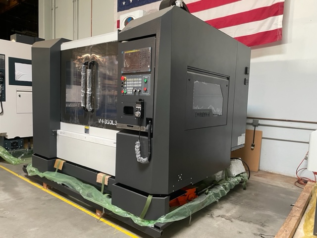
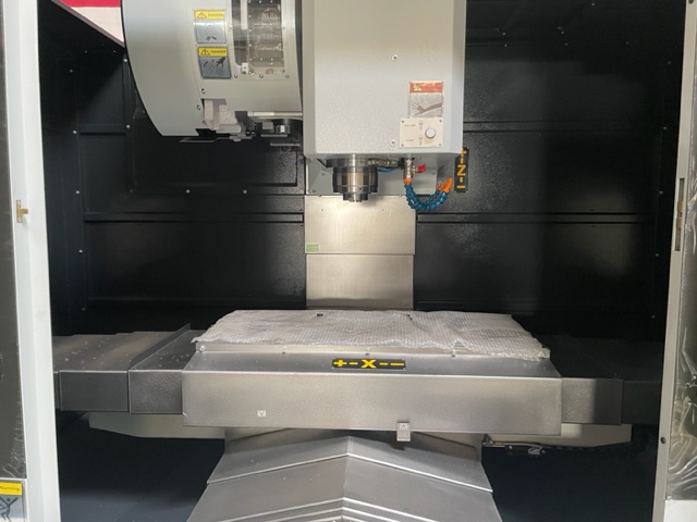
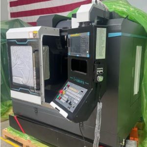
NEW TWINHORN VH-850L3 VERTICAL MACHINING CENTER $79,900
Description
TWINHORN VH-850L3 VERTICAL MACHINING CENTER $79,900
STANDARD FEATURES
► Fanuc Oi-MF Plus 10.4” Color LCD ► Fanuc 20HP Spindle Motor
► 512Kbyte / 800 Meter Memory ► Spindle CAT-40 with 8000 RPM
► PCMCIA Slot for Memory Expansion ► AC Digital Servo & Spindle Drivers
► Helical Interpolation & Custom Macro B ► Arm Type 24 Tool ATC
► High Precision Linear Guide Ways ► Auto Lubrication System
► Meehanite Cast Iron Bed, Base & Headstock ► Fully Enclosed Splash Guard
► Heat Exchanger for Electrical Cabinet ► Spindle Air Blast & Cutting Air Blast
► Automatic Power off (M30) ► Spindle Air Curtain
► Roll Out Coolant Tank & Chip Tray ► RS232 Interface
► Fanuc Operating & Maintenance Manual ► Operating & Electrical Manuals
► 4th Axis Interface Cable only Ready ► Hand Held Coolant & Air Nozzle
► One Year Machine Parts Warranty ► Two Year Control Warranty
MACHINE SPECIFICATIONS
Travel X Axis 33.46” (850mm)
Travel Y Axis 19.69” (500mm)
Travel Z Axis 20.47” (520mm)
Rapid Feed Rate X & Y Axis 1,181ipm
Rapid Feed Rate Z Axis 945ipm
Cutting Feed Rate 390ipm (10 m/min)
Positioning X, Y & Z Axis 0.0001/12” (0.005mm / 300mm)
Repeatability X, Y & Z Axis ±0.0001” (±0.003mm)
Table Dimension 39.37” x 17.72” (1000mm x 450mm)
Maximum Loading 990 lb (450Kg)
Spindle Motor FANUC AC Spindle Motor ßiI 8 / 8000
Spindle Horse Power 20 HP
Spindle Speed 8000 RPM
Spindle Taper CAT-40
Servo Drive Motor X & Y Axis Fanuc ß 12 / 3000is
Servo Drive Motor Z Axis Fanuc ß 22 / 3000is
Distance from Spindle Nose to Table 4.72” – 25.59” (120 – 650mm)
Distance from Spindle to Column 21.26” (540mm)
ATC Swing Arm Type Random, Shortest Path, Bi-Directional
Magazine Capacity 24 Tools
Tool Change Time 2.5 Second
Maximum Tool Weight 15.4 lb (7.0kg)
Maximum Tool Length 11.81” (300mm)
Maximum Tool Diameter 3.14” (80mm)
Floor Space L x W x H 99”x98”x106” (2508mmx2408mmx2700mm)
Power Requirement 220V, 3 Phase, 60Hz, 30kVA, 75Amp
Machine Weight 11,330 lb (5150 kg)
Twinhorn VH-850L3 Machine Specifications 1. HEADSTOCK
- Belt Drive Variable Speed
- Belt Type 920-8YU-40W for 6000 to 8000Rpm
- Belt Type 810-5GT-35W for 12000Rpm
- Spindle Bearings Grade P4
Angular Contact 6000 & 8000Rpm (Front) 7013C DBD P4
Angular Contact 12000Rpm (Front) 65BNC10-DB
Contact Angle 15 º
O.D 3.937” (100mm)
I.D 2.559” (65mm)
Width 0.709” (18mm)
Angular Contact 6000 & 8000Rpm (Rear) 6011
Angular Contact 12000Rpm (Rear) 55BNC10-DB
O.D 3.543” (90mm)
I.D 2.165” (55mm)
Width 0.709” (18mm)
- Spindle Shaft Hardness HRC 60 – 62
- Retention System Bevel Springs 88 pcs
- Holding Force 1,892 lb (860kg)
- Counter Balance Mechanical
- Spindle Orientation Sensor
- Spindle Taper CT or BT40
- Spindle Motor FANUC AC Spindle Motor ßiI 8 / 8000 / 15Hp
- TABLE
- Dimensions
Length 39.37” (100mm)
Width 17.72” (450mm)
- Max. Table Load 990 lb (450kg)
- Slide Ways THK NR Series Linear Guide Ways
- AUTOMATIC TOOL CHANGER (ATC)
- Type Arm Type Random, Shortest Path, Bi- Directional
- Max. Tool Weight 15.4 lb (7kg)
- Max. Tool Length 11.81” (300mm)
- Tool Change Time (Tool to Tool) 2.5 Seconds
- Magazine Capacity 24 Tools
Max. Tool Dia. (Adjacent Pot Tooled) 3.14” (80mm)
Max. Tool Dia. (Adjacent Pot Empty) 4.92” (125mm)
- X AXIS
- Ballscrew Diameter 1.57” (40mm)
Lead 0.47” (12mm)
Accuracy C3
- Drive Motor Fanuc B12/3000i Motor
- Thrust (Continuous) 1518 lb (690kg)
- Rapid Rate (Linear Way) 1,181ipm (30 m/min)
- Rapid Rate (Box Way) 787ipm (20m/min)
- THK Linear Way NRS30R3-1640
- Travel 33.46” (850mm)
- Positioning 0.0001”/12”
- Repeatability ± 0.0001”
- Y AXIS
- Ballscrew Diameter 1.57” (40mm)
Lead 0.393” (10mm)
Accuracy C3
- Drive Motor Fanuc B12/3000i Motor
- Thrust (Continuous) 1518 lb (690kg)
- Rapid Rate (Linear Way) 1,181ipm (30 m/min)
- Rapid Rate (Box Way) 787ipm (20 m/min)
- THK Linear Way NRS35R2-1080
- Travel 19.69” (500mm)
- Positioning 0.0001”/12”
- Repeatability ± 0.0001”
- Z AXIS
- Ballscrew Diameter 1.57” (40mm)
Lead 0.393” (10mm)
Accuracy C3
- Drive Motor Fanuc B12/3000i Motor
- Thrust (Continuous) 1518 lb (690kg)
- Rapid Rate (Linear Way) 945ipm (24 m/min)
- Rapid Rate (Box Way) 787ipm (20 m/min)
- THK Linear Way HSR45LR2-1095
- Travel 20.47” (520mm)
- Positioning 0.0001”/12”
- Repeatability ± 0.0001”
- COOLANT SYSTEM
- Coolant Motor Type CH2-30 / 780W-60HZ
- Pump Capacity 33.3 L / min-0.3bar
- Coolant Tank Volume 200L
- Coolant Flush System (Option) CH2-30*2
- FLOOR SPACE REQUIREMENTS
- Length 98.74” (2508mm)
- Width 94.80” (2480mm)
- Height 106.30” (2700mm)
- PACKING SIZE
- Standard Machine 109.76” x 97.63” x 96.46” (2788 x 2480 x 2450mm)
- WEIGHT
- Net 11,330 lb (5150kg)
- POWER REQUIREMENTS
220 Volt 208/220 VAC, 3 Phase / 75 Amps
440 Volt 220-440 3 Phase Transformer / 15 KVA
Fanuc Oi-MF Standard Features:
*Max Controlled axis (5 axes) *Controlled path (1path)
*Max Controlled axis in each path (5 axes) *Axis control by PMC Max 4 axes
*Max Simultaneously controlled axes (Max 4 axes) *Designation of Spindle axes (2 axes)
*Cs contouring control (each path/Total 1 axis) *Axis synchronous control
*Tandem control, Torque control *Control axis detach
*Increment system IS-A, IS-B *Increment system C 0.0001mm, 0.0001deg, 0.00001inch
*Flexible feed gear (Optional DMR) *HRV2 control, HRV3 control
*Inch/metric conversion *Interlock & Machine lock all axes
*Emergency stop / Overtravel *Stored stroke check / Stroke limit external setting
*Mirror image each axis *Servo off / Mechanical handle
*Unexpected disturbance torque detection function *Position switch
*Automatic operation, MDI operation *DNC operation, DNC operation with memory card
*Schedule function, Program number search *Sequence number search, Program restart
*Manual intervention and return *Wrong operation prevention
*Retraction for Rigid tapping, Buffer register *Dry run, Single block, Jog feed
*Manual reference position return *Reference position setting without DOG
*Reference position setting with mechanical stopper *Reference position return speed set
*Reference position shift *Manual handle interruption
*Manual handle feed *Incremental feed
*Jog and handle simultaneous mode *Nano interpolation
*Positioning G00 *Single direction positioning G60
*Exact stop mode G61 *Tapping mode G63
*Cutting mode G64, Exact stop G09 *Skip G31, Reference position return G28
*Reference position return check G27 *Plane selection G17, G18, G19
*Linear interpolation, Circular interpolation *Dwell in seconds and dwell in revolution
*Cylindrical interpolation *Helical interpolation
*Thread cutting, synchronous cutting *High-speed skip, input signal is 4 point
*Torque limit skip *2nd/3rd/4th reference position return
*Normal direction control *Index table indexing, General purpose retract
*Rapid traverse rate, Rapid traverse override *Feed per minute, Feed per revolution
*Without position coder feed per revolution *Without position coder constant surface speed control
*Tangenitial speed constant control *Cutting federate clamp
*Automatic acceleration/deceleration *Rapid traverse bell-shaped acceleration/deceleration
*Linear acceleration/deceleration after cutting feed interpolation
*Feedrate override 0-254% *One-digit F code feed, Inverse time feed
*Jog override 0-655.34% *Override cancel, External deceleration
*Automatic corner deceleration *Feedrate control with acceleration in circular interpolation
*Rapid traverse block overlap *Al advanced preview control
*Tape code EIA/ISO *Label skip, Parity check, Control in/out
*Optional block skip 9 *Max programmable dimension ±9 digit
*Program number O4 digit *External memory and sub program calling function
*Sequence number N5 digit *Absolute/incremental programming
*Decimal point programming/ pocket calculator type decimal point programming
*Input unit 10 time multiply *Diameter/radius programming
*Rotary axis designation, Rotary axis roll-over *Polar coordinate command
*Coordinate system setting *Automatic coordinate system setting
*Workpiece coordinate system G52-G59 *Workpiece coordinate system preset
*Addition of workpiece coordinate system 48 pairs *Direct input of workpiece origin offset value measured
*Manual absolute on and off *Optional chamfering/corner R
*Programmable data input G10 *Programmable parameter input
*Sub program call 10 folds nested *Custom macro
*Addition of custom macro common variables #100 – #199, #500 – #999
*Interruption type custom macro *Canned cycle for drilling
*Circular interpolation by R programming 9 digit *Automatic corner override
*Scaling *Coordinate system rotation
*Programmable mirror image *Tape format for Fanuc Series 10/11
*Small-hole peck drilling cycle *Pattern data input
*Conversational programming with graphic function
*Auxiliary function (M8-digit) *2nd auxiliary function (B8-digit)
*Auxiliary function lock *High speed M/S/T interface
*Multiple command of auxiliary function *Spindle speed function S5 digit, binary output
*Spindle serial output S5 digit, serial output *Spindle analog output S5 digit, analog output
*Constant surface speed control *Spindle override (0 – 254%)
*Spindle orientation (1 spindle) *2nd spindle orientation
*Spindle output switching function (1 spindle) *2nd spindle output switching function
*Spindle synchronous control *Rigid tapping
*Tool function (T8 digit) *Tool offset pairs (400 pairs)
*Tool length offset *Tool offset
*Tool radius/Tool nose radius compensation *Tool length measurement
*Automatic tool length measurement *Tool life management
*Extended tool life management *Backlash compensation
*Backlash compensation for each rapid traverse and cutting feed
*Store pitch error compensation *Part program storage 320Kbyte
*Number of registerable programs (400) *Part program editing
*Program protect, Password function *Extended part program editing
*Playback *Background editing
*Status display, Clock funtion *Current position display
*Program comment display (program name 31 characters)
*Parameter setting and display *Parameter check sum function
*Alarm display, Alarm history display *Operator message history display
*Operation history display *Run hour and parts count display
*Actual cutting federate display *Display of spindle speed and T code at all screens
*Directory display of floppy cassette *Directory display and punch for each group
*Operating monitor screen *Servo setting screen, Spindle setting screen
*Servo waveform display *Maintenance information screen
*Software operator’s panel *Software operator’s panel general purpose switch
*Extended software operator’s panel general purpose switch
*Multi-language display *Dynamic display language switching
*Data protecting key (4 types) *Erase CRT screen display (manual or automatic)
*Parameter setting support screen *Help function
*Self-diagnosis function *Periodic maintenance screen
*Display of hardware and software configuration *Servo information screen
*Spindle information screen *Graphic display
*Reader/puncher interface Ch 1, Ch2) *External tool offset
*External machine zero point shift *External massage
*External data input (including external tool offset, external message)
*External key input *External program input
*External workpiece number search *External program number search (1 – 9999)
*Memory card input/output *Screen hard copy
*Power Mate CNC manager *External I/O device control
*Embedded Ethernet

